Making a cylindrical metal bar resonate is fairly simple but
takes practice. We use a cylindrical aluminum bar which is normally inserted
into a bushing in a counter and used for supporting chemistry lab apparatus. The
bar is slightly less than a meter long (98 centimeters) and two centimeters in
diameter. While our aluminum rod seems to work very well, copper or steel rods
or tube also work well. Shorter bar or tubes give a higher pitch.
Longer ones a lower pitch.
To make the bar resonate first rub a generous amount of rosin
on its surface. The type used on violin bows which is available in any good
music store works well. Next grasp the bar between the thumb and first finger of your
left hand exactly at the rod’s center. This is easy to find since it is the
"balance point" of the bar. Finally, grasp the bar near your left hand
with the thumb and first finger of your right hand. Pull the thumb and first
finger of your right hand along the bar’s surface while grasping it with a
uniform pressure. At all times maintain your grip on the center of the bar with
your left hand as the right hand slides toward the end of the rod.
The bar vibrates with a standing wave which has a node at its center.
The molecules near a node remain essentially stationary even though the rod is vibrating.
This allows one to grip the rod at this position
without disturbing the sound. The end of the rod is free to move and forms an anti-node which has a
maximum amount of movement in the bar's molecules. Although the antinode’s movement is too small to
detect visually, its presence can be demonstrated by touching the end of the
rod. When this is done the sound immediately stops.
A standing sound wave is caused by the reflection of sound
waves traveling in the bar. When a wave hits the end of the bar it is reflected
backwards. Since the end of the bar is free to move the reflected wave is in
phase with the original wave and reinforces it's peaks forming an interference
pattern with fixed positions for nodes and antinodes.
You may have to rub the rod several times before it starts
resonating. This begins as a faint sound. Continue adding energy to the rod by
rubbing it until it reaches an ear piercing level. Do not attempt this in front
of an audience or class until you have fully mastered the technique! In the
beginning almost no one can do it, but this is part of the fun. Everyone wants
to try and it is wicked entertainment to watch them as they fail. We once did this for an entire day at a
street fair. The local television sports caster was about the only person to
succeed. Not to be bested by a bunch of nerds, he worked with a determined look
on his face for about 20 minutes until he produced the ear splitting noise.
Despite our congratulations and slaps on the back, he didn’t, however, ask us
to be on TV.
Impressive as the demonstration is, it raises an equally large number of
questions. First, why does the rod resonate at only one harmonic frequency? Most
musical instruments use a similar principle but do not sound irritating since
they produce a wealth of harmonic sounds. Second, if the rod can only be gripped
in the center and if touching the end immediately stops the noise, how is it
possible to rub the rod without damping the vibrations?
We start our analysis by determining the rod’s natural frequencies. Figure
1. shows a diagram of the standing waves and the positions of nodes and
anti-nodes for the first three harmonic frequencies. They are:
- f1 = v/(2L)
- f2 = v/L
- f3 = 3v/(2L)
-
- Where:
- L = the length of the rod
- v = the velocity of sound in aluminum
Clearly the second harmonic is unlikely since it would have an anti-node in
the middle of the rod. This would likely be damped out by grasping the rod.
|
|
 |
| |
|
| Figure 1.
Diagram of the First Three Harmonics of a Vibrating Bar |
The next logical step is to analyze the sound output of the
rod by making the rod resonate with a high loudness level. It's best to keep this
burst of sound as short as possible or use ear
plugs if done for lengthy periods. Lower loudness levels don’t always yield a
pure sine wave. A short sound segment was recorded into a
microphone connected to a Vernier MPLI system installed in a desktop computer
with MPLI software.
This particular system is no longer available but the same experiment can be done
with a Texas Instruments TI-83 and CBL or with a Vernier LabPro connected to a
computer.
|
When the MPLI software is set for chart recording
it gives a loudness verses time plot.
When the MPLI software is set to
fast Fournier
transform (FFT) mode it gives an amplitude
verses frequency plot. This is especially useful for detecting resonance
frequencies. They appear as very high peaks on the FFT plot.
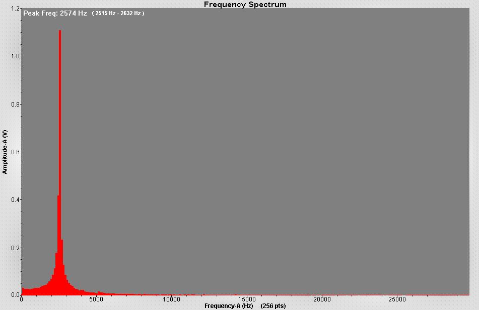
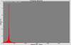
The FFT plot gives a
single frequency for our rod of 2574 Hz (see
Figure 3). The
frequency from the loudness verses time plot is the reciprocal of
the time between two loudness peaks. Figure 2. shows that the time between peaks
is about .004 seconds. This gives a frequency of 2500 Hz. Generally the FFT and calculated
frequencies are in close agreement.
If we assume that the single frequency is the first harmonic we can calculate
the velocity of sound using the following formula:
v = (f1)(2L)
Using the 2574 Hz from the FFT plot gives a
velocity of sound in aluminum of 5045. This compares well with the textbook
value of 5000 m/s. Such close agreement confirms the hypothesis that we do indeed hear the first harmonic.
|
|
|
| Figure 2.
Microphone Output vs Time for a Resonating Rod
|
| |
| Figure 3. FFT Graph of
Microphone Output for Resonating Rod |
|
 |
|
Drums, pipe organs, guitars and just about all forms of acoustic musical
instruments work by vibrating at natural frequencies but do not sound irritating
because they contain many harmonics. By contrast we hear only one frequency with
our rod.
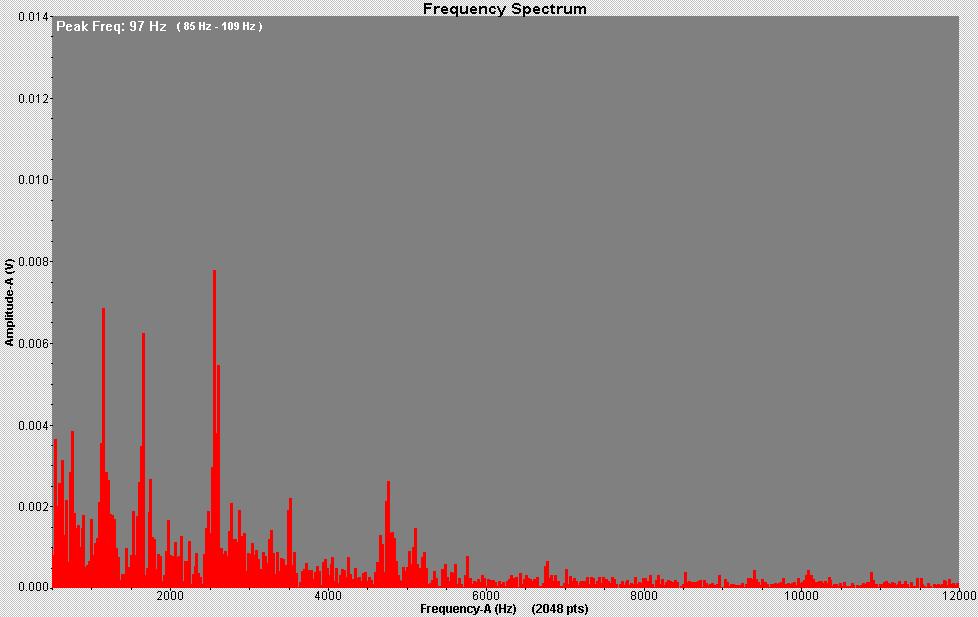
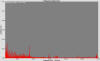
| The likely explanation for the single frequency is that the
bar is not being excited at any of its higher harmonics. To test this we
attach the microphone to the end of the bar with a rubber band and rub the
bar while recording the
results in the FFT display. Typically this shows multiple frequencies similar to
white noise (see Figure 4.). However, the highest exciting frequency is less than
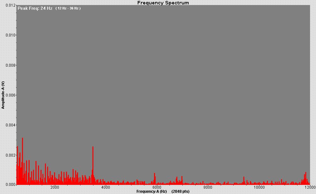
the third harmonic of the bar. Using poor technique does not make the bar
resonate because it does not input enough energy in a frequency corresponding to any of the
bar’s harmonics (see figure 5). This explains why most people cannot perform
the trick without a significant amount of practice. |
|
| Figure 4. FFT Graph
of microphone Output With Effective Technique |
|
 |
|
| |
|
| |
|
Figure 5. FFT Graph of microphone
Output With Ineffective Technique |
|
 |
|
The single biggest factor in making the bar
resonate seems to be the amount of rosin on the bar. Rosin creates a high static
friction between the bar's surface and a person's fingers. Static friction
occurs when no sliding is present and prevents sliding from happening at least
up to a point. When the shear stress between surfaces reaches a critical level
they break lose and slide. The friction becomes dynamic which is much lower than
the static friction and the high shear stress is temporarily relieved. The lower
shear force allows the sliding to stop. This cycle is called stick slip and
continuously occurs as the bar is rubbed. The stick slip action cases the
vibration with results in resonace.
The final mystery to be answered is why rubbing the
bar does not damp out the
vibrations. If the bar vibrated with a transverse wave which caused movement perpendicular to the bar’s axis, the gripping action of sliding fingers would
damp the vibrations enough to prevent resonance. Since this does not happen, the
vibrations must be longitudinal or in the same direction as the bar’s axis. In
this case the gripping action would cause far less damping especially at low
levels of vibration.
We spent a long time pondering how to confirm this experimentally. We wanted
to use cool stuff like laser beams, high speed photography through microscopes
etc. but in the end, used a child’s xylophone striker. Holding the center of
the bar, we carefully pinged the end in a longitudinal direction (the direction
of the rod's axis) and analyzed the results with FFT. We repeated the experiment with a
transverse ping on the rod's side (perpendicular to the axis) and again recorded
the results. Theoretically, a longitudinal ping should create a longitudinal
wave, etc. As seen in figure 6 the longitudinal wave’s dominate peak perfectly
matches the resonating sound’s frequency while the transverse wave’s sound
spectrum is considerably different. This supports the hypothesis that the
resonating bar’s vibration is in a longitudinal direction.
This analysis can be done even without FFT
equipment. For most listeners the noise from the longitudinal ping sounds
remarkably like the resonating bar’s sound although much quieter. The sound of
striking the bar in the transverse direction is completely different.
The sound spectrum from the longitudinal ping
contains not just the first harmonic but also an additional smaller peak.
Calculations show that it matches the third harmonic of the bar. The action of
the striker hitting the end of the bar excites more of the high level harmonics
than rubbing the bar's side. Indeed, striking an object and measuring the
resulting vibrations is considered by engineers to be one of the ways to
identify potential resonate frequencies.
Good lab technique with the striker makes a distinct difference in the
analysis of the rod. A light ping seems to work better than a heavy one. Also
care needs to be taken to hit the rod either exactly perpendicular to its axis
to cause the transverse wave or in exactly the same direction as its axis to
cause the longitudinal wave. Errors in technique will result in simultaneously
exciting the bar in both the transverse and
longitudinal directions since the striker will have a momentum component in both
directions.
To further confirm the longitudinal nature of the bar’s vibrations, we
tried gripping the end of the bar in the transverse direction as it was
resonating. While this does damp the vibrations and reduce the sound level the
effect is far less dramatic than touching the end of the bar.
Although this series of experiments is not for beginners, it is dramatic and
yields satisfying agreement between theory and measured results. The fact
that broad spectrum sound input to the bar’s sides is emitted as intense
single frequency noise from the bar’s ends is strikingly similar to the way a
laser beam works. Whether done as formal experiments or as demonstrations the
resonating bar always leads to stimulating physics discussions and a sense of
wonder at the power of resonance.